Acrylic – Panels
|
Title |
CRACKED ACRYLIC PANELS |
|
Date |
2012 |
|
Objective |
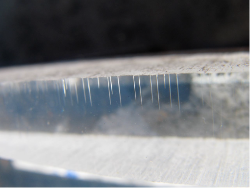
To investigate the root cause of cracking of acrylic panels used as decorative cladding panels on a foot bridge in NZ. |
|
Photo |
Figure 1. Cracking around mounting holes
Figure 2. Resistance to ESC. Cracking observed on bent strip only where adhesive film was applied |
|
Testing Undertaken |
Failure Analysis Methodology (Scheirs 2000) Determination of Resistance to Environmental Stress Cracking (ESC) ISO 22088-3: 2006 GC/MS |
|
Failure Analysis |
Cracking of the acrylic sheet was typical of ESC and Cyclic Stress Loading (CSL). Computer modelling showed that the panels were subjected to high strains concentrated around the mounting holes due to thermal stresses andwind gusting in service. The adhesive backed decorative film applied to the acrylic panels was the most likely root cause of the stress cracking owing to the various potent stress cracking chemicals detected in it. |
Acrylonitrile butadiene styrene (ABS) – Mesh for work platforms
|
Title |
UV RESISTANCE TESTING |
|
Date |
2012 |
|
Objective |
To further study the UVResistance of two different supplied plastics samples |
|
Photo |
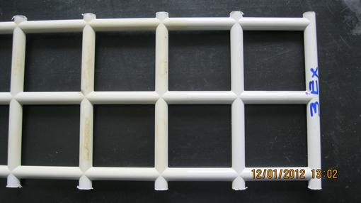
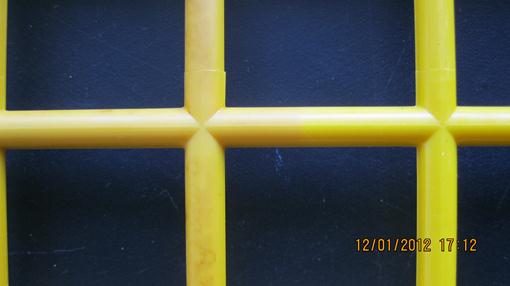
Figure 1a and 1b. Grey Mesh after UV exposure showing slight discolouration
Figure 1a and 1b. Yellow Mesh after UV exposure showing slight discolouration |
|
Testing Undertaken |
Strips of mesh that had previously undergone accelerated UV aging were re-loaded into a QLabs UV Weatherometer and exposed to a second period of accelerated UV aging. The samples were then visually inspected. |
|
Failure Analysis |
Visual inspection of both the grey and yellow mesh samples showed some dis-coloration but no evidence of substantial polymer degradation. |
Acrylonitrile butadiene styrene (ABS) – Mouldings
(1 of 3)
|
Title |
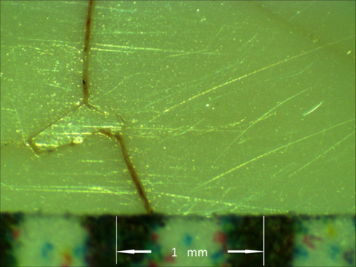
CAUSE OF CRACKING ON AN ABS ASSEMBLY |
|
Date |
2013 |
|
Objective |
To determine the cause for the cracking of an ABS drain assembly |
|
Photo |
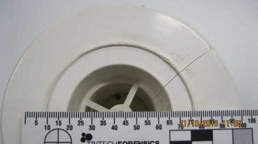
Figure1. Sample showing major lateral crack
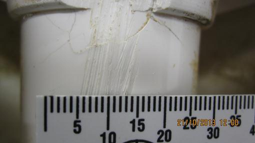
Figure 2. Sample showing cracks at side of moulding
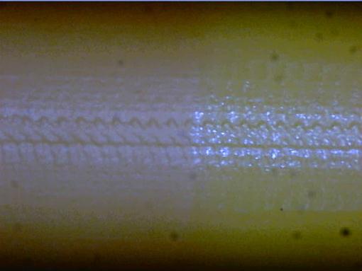
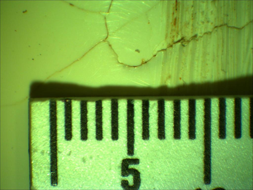
Figure 3. Magnified image of side cracks
Figure 4. Detailed image of crack structure |
|
Testing Undertaken |
Infrared measurement to determine relative quantities of acrylonitrile in materials Visual assessment of nature of cracks using microscope at various magnification. |
|
Failure Mode |
The moulding cracked due to environmental stress cracking caused bycyclohexanone in the adhesive used during assembly. IR-spec indicated no deficiency in acrylonitrile content. |
Acrylonitrile butadiene styrene (ABS) – Mouldings
(2 of 3)
|
Title |
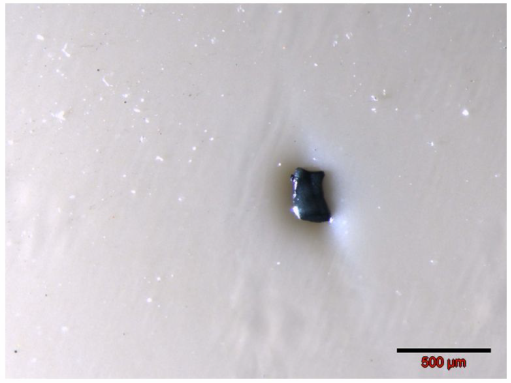
DEFECTS IN ABS USED FOR PLATING |
|
Date |
2013 |
|
Objective |
To investigate the origin of defects in ABS mouldings used for plating |
|
Photo |
Figure 1. Sample 5 |
|
Testing Undertaken |
Microtoming Grazing Angle Optical Microscopy (GAOM) SEM Microprobe Elemental X-ray Analysis (EDAX) |
|
Failure Analysis |
The defects in the ABS mouldings and plated ABS could be attributed to: carbonized black specks rich in bromine (poorly purged extruder), and blue pigment particles based on ultramarine blue (poorly purged extruder). The black specs may also be related to the use of recycled ABS which has additional heat histories |
Acrylonitrile butadiene styrene (ABS) – Mouldings
(3 of 3)
|
Title |
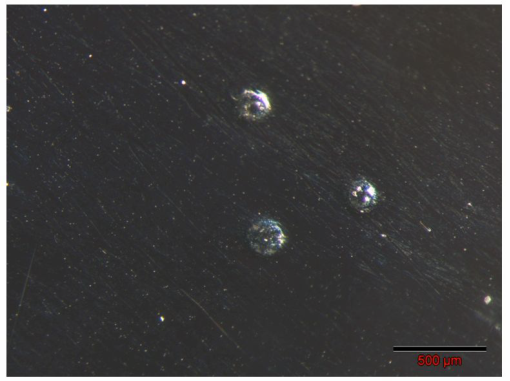
DEFECTS IN ABS USED FOR PLATING |
|
Date |
24 May 2013 |
|
Objective |
To investigate the origin of defects in plated ABS mouldings. |
|
Photo |
Figure 1. Sample 26 (Chrome Plated) |
|
Testing Undertaken |
Microtoming Grazing Angle Optical Microscopy (GAOM) SEM Microprobe Elemental X-ray Analysis (EDAX) |
|
Failure Analysis |
The defects in the plated ABS could be attributed to: pimples formed by surface bubbles (due to gas evolution from surface contamination or hydrogen bubbles) and silica or sand contamination (on one sample). |
Crosslinked polyethylene (PEX) – Hot water pipe (1 of 2)
|
Title |
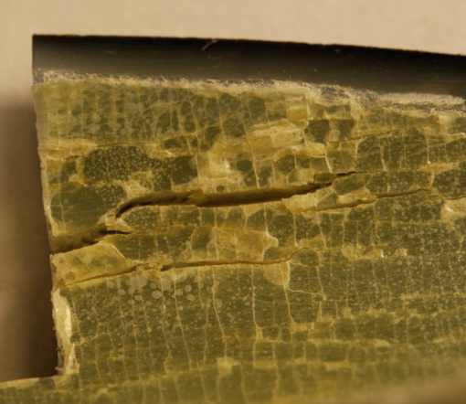
FAILURE ANALYSIS OF PEX HOT WATER PIPE |
|
Date |
2013 |
|
Objective |
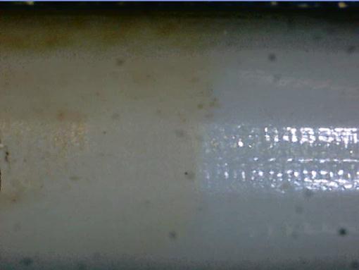
To conduct a failure analysis on samples of PEX pipes that have cracked in service (a hot water system) |
|
Photo |
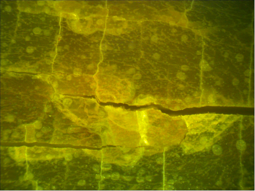
Figure 1. Sample internal surface (Low Mag.)
Figures 2. Internal cracks on sample (40x Mag.) |
|
Testing Undertaken |
Wall thickness measurements Photomicroscopy ATR-FTIR Carbonyl Index per ASTM F2102 OIT by DSC per ASTM D3895 Degree of crosslinking per AS2492 |
|
Failure Mode |
The inner surface of the PEX pipe is totally degraded and embrittled down to ~ 2/3rd total |
Crosslinked polyethylene (PEX) – Hot water pipe (2 of 2)
|
Title |
CRACKING OF PEX HOT WATER PIPE |
|
Date |
2013 |
|
Objective |
To investigate the cause of failure of a sample of PEX black hot water pipe |
|
Photo |
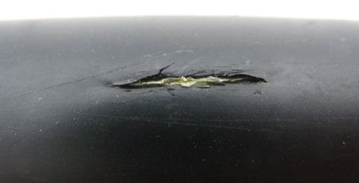
Figure 1. Pipe showing brittle slit failure
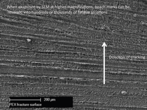
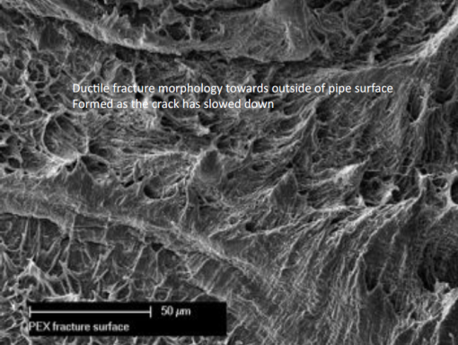
Figure 2a and 2b. SEM Photo of fracture surface through wall of pipe |
|
Testing Undertaken |
SEM Fractographic analysis OIT (per ASTM D-3895) |
|
Failure Analysis |
The pipe failed prematurely by Fatigue Crack Propagation initiated at the inner surface. |
Elastomer – Safety wear (kneepads)
|
Title |
FLEX CRACK TESTING OF KNEEPADS |
|
Date |
2013 |
|
Objective |
To investigate the flex fatigue crack resistance of two kneepads. |
|
Photo |
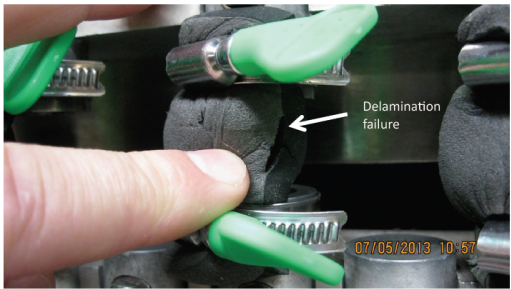
Figure 1. Failure after 1,000,000 flex cycles |
|
Testing Undertaken |
Flex cracking resistance of rubbers and elastomers by AS 4878.9-2001 |
|
Conclusion |
Delamination failure was observed for the rectangular knee pad at the interface between the black rubber and the grey foam after 1,000,000 cycles. |
Epoxy – Castings
|
Title |
ASSESSMENT OF A CRACKED EPOXY CASTING |
|
Date |
2013 |
|
Objective |
To assess the cause of cracking in a moulded epoxy casting. |
|
Photo |
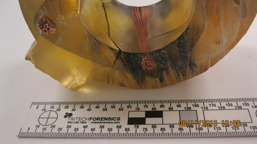
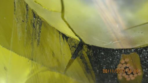
Figure 1. Crack in Casting
Figure 2. Close up of crack in moulding |
|
Testing Undertaken |
Failure analysis |
|
Failure Mode |
Temperature at time of mixing components estimated to be as high as 50°C, possibly causing the reaction to proceed four times faster than normal and generate four times as much heat. This could create a crack due to the thermal stresses generated. |
Epoxy – Sewer Pipes
|
Title |
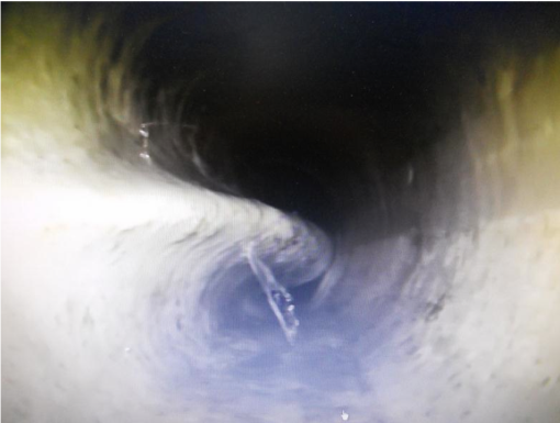
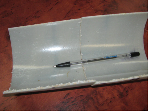
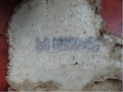
FAILURE ANALYSIS OF COLLAPSED POLYMER LINER IN SEWER PIPE |
|
Date |
2012 |
|
Objective |
To investigate the cause of failure of an epoxy liner in a sewer relining application |
|
Photo |
Figure 1. Photograph of failed liner in situ
Figure 2. Photograph of cured reference liner
Figure 3. Photograph of recovered liner section |
|
Testing Undertaken |
DSC Thermal Analysis IR-Spec Durometer Shore D Hardness Measurements |
|
Failure Analysis |
There were some dry felt areas on the recovered liner, thus indicating resin poor zones suggesting the liner may not have been properly impregnated with epoxy resin. The cured liner has limited stress resistance and thus should not be in a load bearing service application as it lacks ring crush resistance and buckling resistance |