Reinforced polypropylene – Water pipes
|
Title |
Analysis of PP-R Green Pipe |
|
Date |
2013 |
|
Objective |
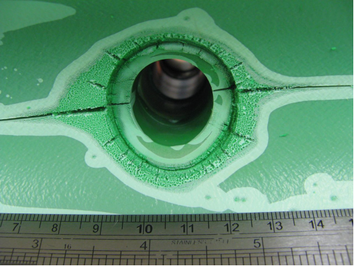
To analyse a sample of PP-R green pipe to determine the cause of cracking failure |
|
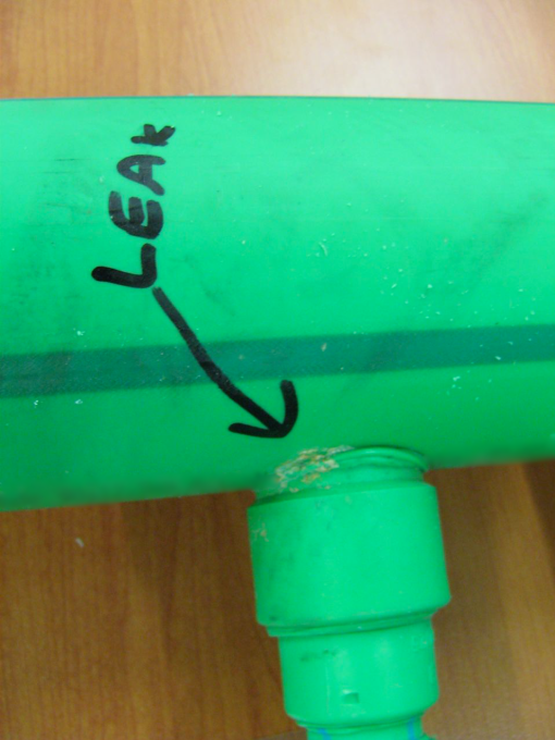
Photo |
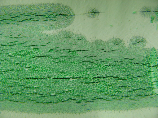
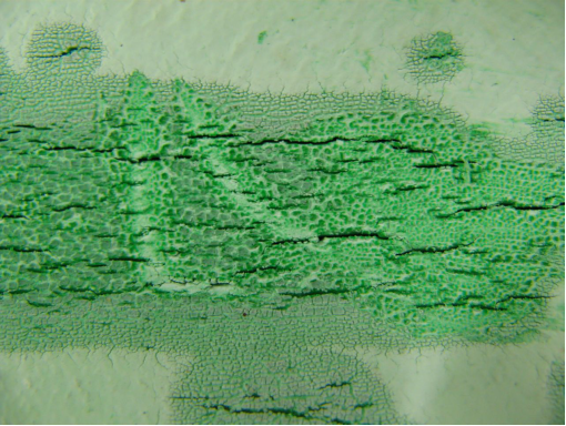
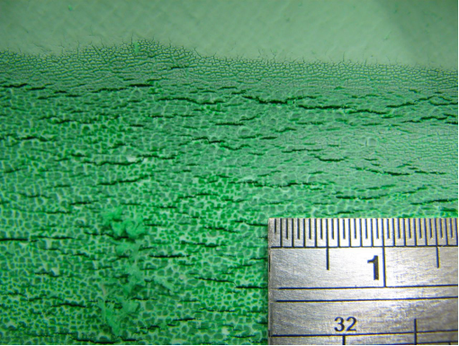
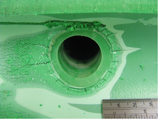
Figure 1. Position of leak on outside of pipe
Figure 2a, 2b, 2c, 2d, 2e. Photomicroscopy of inside of pipe |
|
Testing Undertaken |
OIT as per ASTM D3895 Digital microscopy FTIR as per ASTM F2102 NMR spectroscopy |
|
Failure Analysis |
Antioxidants in the pipe were almost totally depleted (only Irganox 1010 and Irfagos168 were present), thus the pipe was not fit for service. The severe oxidative cracking of the pipe was due to a combination of thermal oxidation and stresses associated with thermal expansion and contraction |
Rubber – Bellows
|
Title |
FAILURE ANALYSIS OF RUBBER BELLOWS |
|
Date |
2012 |
|
Objective |
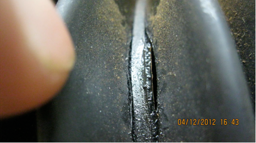
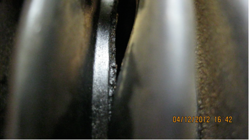
To investigate the cause of cracking of rubber bellows. |
|
Photo |
Figure 1a and 1b. Photomicroscopy showing crack in fold of bellows |
|
Testing Undertaken |
Photomicroscopy IR-Spec |
|
Failure Analysis |
The rubber bellows failed by cracking due to ingress of lithium ions into the nitrile rubber molecular structure. |
Rubber – Floorings
|
Title |
DISCOLORATION OF RUBBER FLOORING |
|
Date |
2013 |
|
Objective |
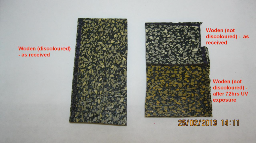
To investigate the discoloration of rubber flooring and in particular to determine the mechanism of yellowing and the root cause of the yellowing. The flooring was installed in various shops. |
|
Photo |
Figure 1. Sample comparison after UV exposure to non-discoloured sample. |
|
Testing Undertaken |
IR Spec analysis (ASTM E1252 – 98) on the exposed surface of the rubber flooring Accelerated UV exposure testing (QUV) (ASTM D7238 – 06) |
|
Failure Analysis |
Yellowing is due to photodegradation of the urethane, which containedchromophores (most likely from the isocyanate precursor) which interact with the UV light leading to poor light stability and photoyellowing. Using chromophore-free isocyanates and/or including UV absorbers would prevent yellowing. |
Rubber – Mouldings
|
Title |
IDENTIFICATION OF A BLACK MOULDED ITEM |
|
Date |
2013 |
|
Objective |
To identify the material from which black item was moulded |
|
Testing Undertaken |
Fourier Transform Infrared (FT-IR) according to ASTM E 573, using an Alpha Measurement Module Digital Scanning Calorimetry (DSC) according to ASTM D 3418, using a DSC Q20 by TA instruments |
|
Conclusion |
Material was most likely a thermoplastic elastomer such as Santoprene (co-polymer of polypropylene and EPDM), as the IR spectrum indicated a polypropylene, EPDM and talc mixture, and the DSC scan showed no crystalline melting point behaviour. IR also showed some unidentifiable absorption peaks. |
Rubber – O-rings
|
Title |
IDENTIFICATION OF RUBBER O-RINGS AND RELEASE AGENTS |
|
Date |
2013 |
|
Objective |
To identify the material in Rubber O-Rings and their release agents. |
|
Testing Undertaken |
The O-rings were washed in chloroform to dissolve the release agents from the O-ring surface. An ATR FTIR spectrometer was then used to measure the IR spectrum of the chloroform wash residue and the washed O-rings. |
|
Conclusion |
The IR spectra of the release agents matched Vaseline. The IR spectra of three of the four O-rings matched butyl rubber. The fourth sample (analysed by Pyrolysis IR spectroscopy) matched an inorganic silicate filled ethylene propylene rubber. |
Silicone – Electrical cables
|
Title |
FAILURE ANALYSIS OF SILICONE |
|
Date |
2014 |
|
Objective |
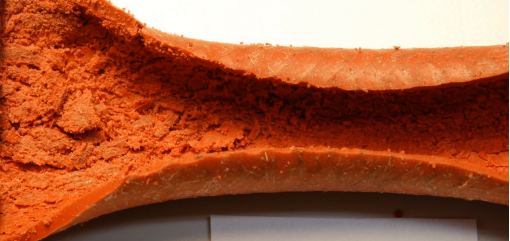
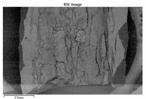
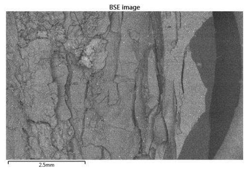
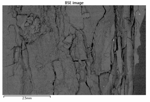
To conduct a failure analysis on the cracked silicone insulated cable to determine the root causes for the herniating of the cables from a materials perspective. The cables were part of a 75kW electric motor that drives a jet fan in a highway tunnel. |
|
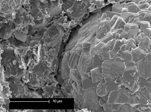
Photo |
Figure 1. Faulty silicone sample
Figures 2a, 2b, 2c. BSE images of failed silicone samples |
|
Testing Undertaken |
Ashing at 600°C Elemental Analysis by EDAX SEM Thermogravimetric analysis from RT to 700 °C |
|
Failure Mode |
Silicone insulation failed by embrittlement due to thermal degradation. The cable is apparently rated for 300 °C but turned brittle at lower temperatures (‘good’ silicone sample turned brittle after just 97 hours at 240 °C). The thermogravimetric scans showed that both silicone samples began to degrade at 250 °C, thus the silicone is not properly heat stable and was likely exposed to high conductor temperatures. The observed degradation of the film also suggested the cables were exposed to excessive temperatures around 300 °C |
Silicone rubber – Seals
|
Title |
FAILURE ANALYSIS OF A SEAL ON A GLASS CONTAINER |
|
Date |
2012 |
|
Objective |
To investigate the cause of a silicone rubber seal sticking to glass and undergoing damage on removal. |
|
Photo |
Figure 1. Failed seal showing loss of material at failure site
Figure 2. Seal showing areas of cohesive failure
Figure 3. Difference in gloss levels between good (dull) and bad (glossy) samples |
|
Testing Undertaken |
IR-Spec Microscopy |
|
Failure Analysis |
The glossy surface of the ‘bad’ silicone rubber has led to ‘auto-adhesion’ on the glass and this in turn has led to cohesive failure of the silicone. Use of a less glossy silicone, or one containing an anti-block additive (such as silica), or a grade of silicone with a higher tear strength value is recommended. |

Teflon – Flakes
|
Title |
IDENTIFICATION OF WHITE FLAKES |
|
Date |
2013 |
|
Objective |
To identify the composition of white flakes |
|
Testing Undertaken |
IR spectroscopy DSC |
|
Failure Mode |
Both tests indicated the white flakes consist of Teflon |
Thermoplastic – Mouldings
|
Title |
ANALYSIS OF BLOOMING ON A THERMOPLASTIC DASHBOARD MOULDING |
|
Date |
2013 |
|
Objective |
To investigate the chemical nature of the blooming species on the surface of thermoplastic dashboard mouldings (which are allegedly causing respiratory issues to users of the vehicles) |
|
Testing Undertaken |
Surface ATR-FTIR Spectroscopy Surface solvent swap followed by NMR ToF-SIMS |
|
Conclusion |
The blooming residue on the surface of the mouldings was composed of glycerolmonostearate (GMS) and related glycerol monooleate (GMO). Both are safe additives which pose no toxicity issues or chemical respiratory symptoms. |
Thermoplastic polyurethane
– Layflat hoses
|
Title |
IMMERSION TESTING OF TPU LAYFLAT HOSE SAMPLES |
|
Date |
2012 |
|
Objective |
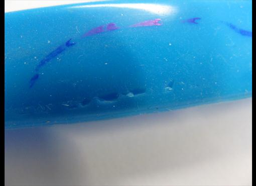
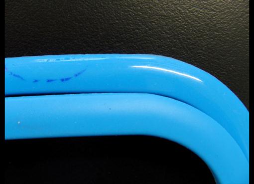
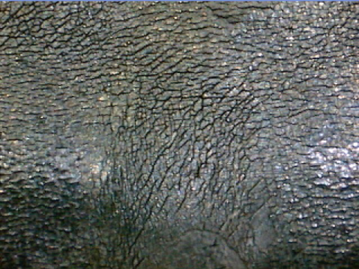
To investigate the cause of observed cracking of layflat hose carrying potable water in the field and to investigate the susceptibility to cracking of various layflat hose samples in aqueous chlorine solutions whilst under stress. |
|
Photo |
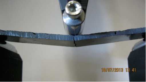
Figure 1. Used 1.0% free chlorine. Note extensive microcracking |
|
Testing Undertaken |
Chlorine Exposure Testing (under bending stress) Digital Microscopy (50x) |
|
Failure Analysis |
The hose failed due to oxidative stress cracking in part caused by chlorine exposure and in part by stress. |
Toner and acrylic paint – Recyclings
|
Title |
CHEMICAL ANALYSIS OF TONER MIXED WITH ACRYLIC PAINT |
|
Date |
2013 |
|
Objective |
To characterise the composition of waste toner mixed with acrylic paint. |
|
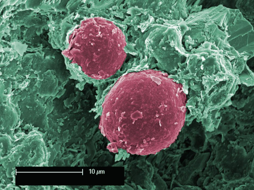
Photo |
Figure 1. EM photo showing good adhesion by Toner particles (red colour)
Figure 2. EM photo showing poor adhesion by ferrite particle
Figure 3. Flexural Testing of Compression Moulded Sample (4 mm displacement & break) |
|
Testing Undertaken |
Thermal Analysis by DSC Electron Microscopy Compression Moulding followed by flexural testing Re-emulsification testing |
|
Conclusion |
Good adhesion between toner phase and acrylic binder is evidence of mutual compatibility and miscibility. Mechanical testing indicated the toner is capable of moderate flexing, however it exhibits brittle behaviour. It is recommended a rubber modifier be added to reduce brittleness. |